Whether you are an engineer finalising a design, a buyer placing an order, or a project manager coordinating a cnc machining project across multiple suppliers, being able to read an engineering drawing accurately is a non-negotiable skill. This guide walks you through every element of a typical manufacturing drawing, from title blocks and tolerances to GD&T symbols and surface finish callouts, so you can communicate clearly with any precision engineering shop in the uk.
Introduction: Why Reading Engineering Drawings Matters in CNC Machining
Elmax Engineering Ltd, founded in 2003 and based in Stockport, Manchester, delivers cnc milling, cnc turning, cylindrical grinding, and keyway slotting for industries including food processing equipment, medical fixtures, construction hardware, and automotive components. Every job that crosses the shop floor starts with a drawing, and precision engineering combines advanced technology with meticulous attention to detail to ensure components fit and function exactly as intended.
Manchester is one of the uk’s leading hubs for advanced manufacturing, and the region has a strong cluster of companies specialising in cnc machining and precision components. While the Midlands are traditional centres for precision manufacturing, Manchester has emerged as a leading hub in its own right. Correctly reading a drawing before metal is cut reduces errors, shortens lead times, and delivers fast turnaround on everything from prototyping to production parts. Misreading a single tolerance on a bearing seat or missing a surface finish note on a hygienic stainless steel shaft can halt an entire production line.
Key benefits of drawing literacy for anyone involved in the manufacturing process:
- Fewer clarification loops between design office and machine shop, ensuring efficiency across the production process
- Predictable costs, because unnecessary tight tolerances or finishes are identified early
- Inspection-ready parts that meet quality standards first time
- Smoother collaboration on complex projects with tight deadlines
This guide shows how to move from cad files and complex geometries on screen to manufacturable, inspection-ready components on the shop floor.
From CAD Files to Engineering Drawings
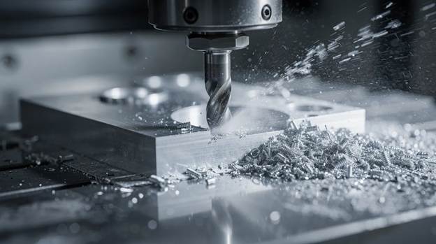
Customers typically send 3D CAD models in STEP, IGES, or Parasolid format alongside fully dimensioned 2D PDF or DWG engineering drawings. Precision engineering relies heavily on CAD/CAM software and computer-guided cnc machining to turn those files into finished parts. The 3D model captures complex geometries and full assemblies, but the 2D drawing defines exact dimensions, tolerances, material requirements, surface finishes, and notes that machinists and inspectors depend on.
A fully defined 2D drawing remains essential for cnc machining services even when multi-axis cnc programming is driven directly from 3D CAD. Here is how the workflow typically runs at Elmax Engineering:
- Client supplies cad files and a fully detailed drawing for quoting
- The CAM team creates toolpaths for cnc milling and cnc turning from the model, referencing the drawing for tolerances and notes
- QA uses the same drawing for first-off and in-process inspection
- Discrepancies between model and drawing are flagged at the quotation stage to prevent costly rework later
For example, a stainless steel shaft destined for the food industry might show curved geometry in the 3D model, but it is the 2D drawing that specifies a hygienic finish of Ra ≤ 0.8 µm and an M6 keyway slot. Prototyping accelerates product development cycles significantly, and prototyping allows for rapid testing of design concepts. Prototyping helps identify design flaws early in the process and can reduce production costs before full-scale manufacturing. Many prototyping projects involve multiple manufacturing processes in one platform.
Core Elements of an Engineering Drawing
Most uk engineering drawings follow BS 8888:2020, the current national standard that replaced BS 308 and aligns UK practice with international ISO standards. Understanding the basic layout is the first step to reading any print. Key aspects of precision engineering include high-accuracy machining and metrology, and stringent regulatory standards drive industry practices in safety-critical markets.
The main zones of a drawing and their functions:
- Title block – part number, material selection (e.g. EN24T, 316L stainless steel), surface finish (e.g. Ra 1.6), scale, projection symbol, originator, checker, approver, and company detail
- Revision block – logs changes to dimensions or specs with date and initials; a bore diameter change directly affects ongoing machining and lead times
- Views – orthographic projections showing part geometry from multiple angles
- Dimensions – linear, diameters, radii, angles with associated tolerances
- Tolerances – general and specific limits controlling accuracy
- Notes – material grade, heat treatment, thread specs, edge breaks, finishing instructions
- Projection symbol – indicates first-angle or third-angle projection, found adjacent to the title block
Precision engineering supports several major industries including aerospace and medical, so drawing completeness is critical for product quality.
Views, Sections, and Projection Symbols
Orthographic projection remains the standard language between design offices and precision engineering shops. In the uk, third-angle projection is standard, identified by the familiar truncated-cone-and-circle symbol next to the title block. First-angle projection is common on mainland European drawings; confusing the two leads to parts machined in mirror image.
Section views expose internal features that standard views cannot show: deep bores, internal oil galleries, gasket grooves, and hidden channels in milled manifolds. Detail views zoom into small critical areas such as keyway profiles or thread roots. Auxiliary views handle inclined features that do not align with the principal planes. Multi-axis cnc turning allows integrated milling capabilities, so understanding which features appear in which view helps machinists at Elmax select the right sequence of operations – cnc turning followed by milling or grinding – before cutting begins.
Dimensions, Units, and Tolerances
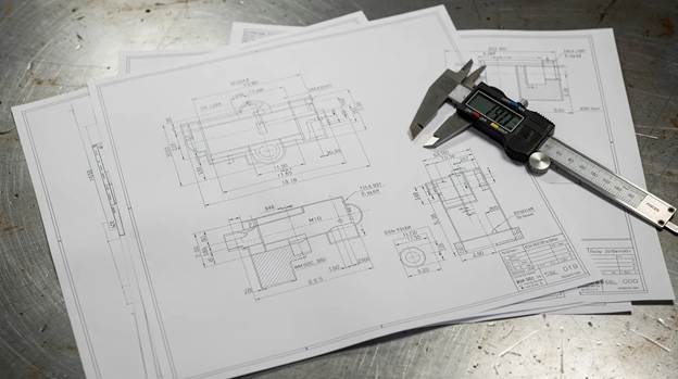
Accurate interpretation of dimensions and tolerances is the backbone of precision cnc machining and cylindrical grinding. Standard units on uk drawings are millimetres, typically stated in the title block as “UNLESS OTHERWISE STATED, DIMENSIONS IN mm.”
Dimension types you will encounter:
- Linear – distance between features
- Diameters – e.g. Ø25.00 ±0.02 for a bearing seat turned on a CNC lathe
- Radii – e.g. R3 corner radius
- Angles – e.g. 45° chamfer
General tolerances are often declared in a note referencing ISO 2768 (e.g. “LINEAR ±0.1, ANGULAR ±0.5°”), while critical features carry specific tolerances. Precision cnc machining achieves tolerances as tight as ±0.005mm, and cnc turning can achieve the same. CNC milling can also achieve tolerances as tight as ±0.005mm, and cnc machining overall can produce parts with tolerances of ±0.005mm. It involves producing parts with tolerances as tight as ±0.005mm where the end use environment demands it.
The ISO 286 hole-basis fit system drives process choice. An H7/g6 sliding fit on a 50 mm bearing seat means the hole is 0 to +0.025 mm and the shaft is −0.009 to −0.025 mm – always a clearance. Achieving that on a shaft usually requires fine cnc turning plus cylindrical grinding, while a standard clearance hole needs only milling. Tight tolerances directly influence machining strategy, inspection plan, and achievable reliable lead times, and Elmax balances precision and cost at the quotation stage.
Geometric Dimensioning and Tolerancing (GD&T) Basics
GD&T is the system that controls form, orientation, position, and runout using feature control frames and datums. Quality is fundamental in safety-critical industries like aerospace, and leading firms employ advanced metrology tools for quality assurance. Xometry, for example, provides First Article Inspection reports for quality verification and includes inspections at multiple production stages. Hemlock Engineering is ISO 9001:2015 certified, reflecting the high standard expected across the industry.
Key GD&T symbols commonly seen on uk manufacturing drawings:
- Flatness – controls surface waviness on clamping faces after cnc milling
- Perpendicularity – e.g. ⊥ 0.02 A B on a flange face relative to a bore axis
- Parallelism – ensures two faces remain within tolerance
- True position – controls bolt-hole PCD on an automotive hub
- Circular runout / Total runout – controls rotating surface accuracy on turned shafts
- Concentricity – less common due to inspection complexity; positional tolerancing often preferred
Datums (A, B, C) relate directly to machining set-ups on 3- or 4-axis cnc machines. Primary datum A might be a bearing face; datum B the shaft centreline. Understanding these lets machinists choose correct fixturing and inspection methods – CMM checks, gauge blocks, or Renishaw probing – ensuring high quality results.
Surface Finish, Treatments, and Machining Notes
Surface finish is specified using the check-mark symbol with Ra values. For food-industry contact surfaces, Ra ≤ 0.8 µm is widely required for hygiene; some dairy applications demand Ra 0.3–0.6 µm. Non-critical areas may allow Ra 3.2 or 6.3. These requirements influence cnc milling and turning parameters, tool selection, speed, and whether secondary operations such as cylindrical grinding or bead blasting are needed.
Advanced materials used in precision engineering include metals, alloys, engineering plastics, and composites. Common drawing notes cover heat treatment (e.g. “EN8 hardened and tempered to 30–35 HRC”), plating (zinc, nickel), and anodising for aluminium parts. Elmax regularly coordinates finishing options including bead blasting before anodising for improved cosmetic appearance on custom parts. A typical “GENERAL NOTES” area might read: “BREAK ALL SHARP EDGES 0.5 × 45°”, “REMOVE ALL BURRS”, “MATERIAL: 316L STAINLESS STEEL”. Ignoring any of these notes risks parts being rejected at goods-in inspection. Precision machining is used to produce parts for laboratory equipment and medical devices where such detail matters.
Title Blocks, Revisions, and Issue Control
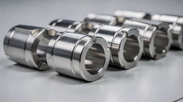
The title block is the single source of truth: part name, drawing number, material, weight, scale, projection type, originator, checker, and approver. Precision engineering involves ensuring thousands of identical components are manufactured with the same quality, and that starts with everyone working from the correct revision.
Revision control uses issue levels (A, B, C). When a customer updates a bore diameter and thread spec, issuing new Rev C dated 12/03/2025, Elmax updates CAM programs, route cards, and inspection sheets before any cutting begins. Inconsistent revision control between drawing and cad files causes rework, longer lead times, and scrap.
Before starting any cnc machining project, always confirm:
- Drawing revision matches the customer’s purchase order
- Material spec and heat treatment are current
- No superseded notes or dimensions remain from a previous revision
- The master definition (3D model vs 2D drawing) is agreed when discrepancies exist
Reading Drawings for CNC Milling, Turning, and Grinding Operations
Elmax engineers read every drawing with manufacturing in mind, identifying which faces to mill first, which diameters to turn, and what sequence minimises distortion and set-ups. Companies in the region integrate design, cnc machining, assembly, and testing under one roof.
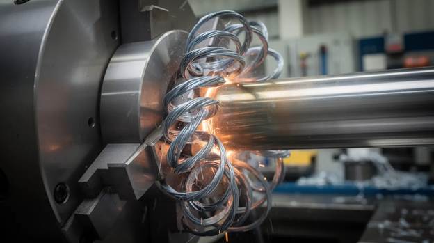
For cnc turning, the drawing’s diameter dimensions, coaxial tolerances, and runout callouts drive the process. CNC turning creates cylindrical parts using rotating material and can produce components from 1mm to 250mm diameter. CNC turning is ideal for parts like shafts and bushings. Firms in Greater Manchester machine high-performance materials like titanium and aluminium on these lathes daily.
For cnc milling, pockets, slots, and complex shapes are defined by section and detail views. CNC milling uses rotary cutters to remove material from workpieces, and 5-axis cnc milling allows for intricate parts in a single setup – sometimes a single operation. Multi-axis cnc milling improves production efficiency and precision. CNC milling is ideal for creating parts with complex shapes and complex geometries.
Cylindrical grinding follows turning when tolerances demand it – typically ±0.005 mm on bearing seats. A flanged shaft might require cnc turning of diameters, milling of key flats, keyway slotting, and final grinding, each step driven by what the drawing specifies. Axis cnc capabilities (3- and 4-axis) determine whether complex geometries are broken into multiple set-ups or combined. Reading the drawing correctly at quotation stage helps Elmax forecast realistic lead times and fast turnaround while maintaining consistent quality.
Common Mistakes When Interpreting Engineering Drawings
Frequent issues encountered by Manchester precision engineering firms include:
- Missing tolerances on critical features so default general tolerances are too loose for bearing seats
- Ambiguous datum specification causing incorrect fixture build-ups
- Conflicting dimensions between views due to CAD-drawing mismatch
- Unspecified surface finishes (“fine finish” instead of a measurable Ra value)
- Projection ambiguity – no symbol or wrong symbol, confusing the machining team
In one case, an automotive bracket’s bolt-pattern spacing was dimensioned on one view but omitted from another, leading to mis-drilled holes, misalignment on assembly, and a week of rework. CNC machining can handle both small-scale and large-scale production runs, but errors like these wipe out any efficiency gains.
To avoid problems on complex projects: double-check critical dimensions, clarify unclear GD&T, and confirm finishes and material requirements before placing orders. Elmax encourages early technical reviews of drawings and cad files to catch issues before metal is cut – an approach that supports reliable lead times and consistent product quality.
How Elmax Engineering Uses Drawings in the CNC Machining Workflow
Elmax’s workflow from enquiry to delivery keeps the engineering drawing central at every stage. The uk cnc machining industry is known for high precision and technology, and Elmax reflects that.
- RFQ review – drawings checked for completeness, tolerances, material, and finish
- Manufacturability assessment – the experienced team flags any features that could cause issues or drive unnecessary cost
- Quotation – realistic pricing based on drawing requirements, production capacity, and tooling needs
- CAM programming and cnc programming – toolpaths generated from the model, verified against the drawing
- First-off inspection – precision parts measured against drawing specs before batch continues
- In-process and final inspection – controlled under ISO 9001 processes with digital and paper copies of the drawing
Elmax supports one-off prototypes, small batches, and mass production runs. Advanced cnc machining includes processes like milling, turning, and grinding, and the team can work with almost any material – stainless steel, aluminium, titanium, copper, brass, plastic, wood, and more. CNC machining services include cnc turning and cnc milling across the full range of materials. This production capacity, combined with automation where appropriate, allows Elmax to deliver precision cnc machining services with reliability and speed across food, medical, construction, and automotive industries. Precision engineering is critical in aerospace, automotive, and medical sectors, and precision engineering is essential for high-performance and reliability.
Checklist: Reading an Engineering Drawing Before You Place an Order
Before sending drawings to a cnc machining supplier, work through these steps to ensure a smooth manufacturing process and high quality results:
- Units – confirm mm or inches; check title block declaration
- Tolerances – verify that critical features (bearing bores, sealing faces, threaded holes) carry explicit tolerances, not just general
- Projection type – confirm third-angle or first-angle; look for the symbol
- Material – check grade matches your design intent and the end use environment
- Heat treatment – specify hardness range and process (e.g. case-hardened, tempered)
- Surface finish – state Ra values on all critical surfaces; note any bead blasting or coating requirements
- GD&T – ensure datums and feature control frames are complete and unambiguous
- Revision level – confirm the drawing is the latest issue and matches the purchase order
- CAD vs drawing – agree which is the master definition when dimensions differ
- Supply both files – provide cad files and fully detailed drawings for complex geometries to streamline quoting and cnc programming
Precision cnc machining services depend on complete, unambiguous drawings. This checklist works as an internal purchasing or engineering aid – print it out and use it every time you place an order.
Conclusion: Turning Drawings into Reliable Machined Parts
Being able to read engineering drawings accurately helps companies get better results from machining services in Manchester and across the uk. Elmax Engineering Ltd turns well-defined drawings into precise custom parts and high precision components – from simple turned pins to complex multi-operation components requiring cnc milling, CNC turning services, grinding, and keyway slotting. The service covers every stage from prototyping through to production, delivering consistent quality and efficient turnaround across industries.
Fewer queries, reduced risk of delay, predictable lead times, and smoother collaboration on complex projects – these are the tangible benefits of drawing literacy. If you are planning your next cnc machining project, share your drawings and cad files with the Elmax team in Stockport, Manchester, for feedback on manufacturability, tolerance choices, and cost-effective process combinations. Get in touch to produce your next batch of precision parts with the accuracy and reliability your project demands.


Leave a comment